- 0755-21675210
- acdrive@micno.com.cn

2023-05-03
Introduction
A high-speed wire drawing machine is one of the main equipment for metal wire processing, mainly for processing metal wire into various specifications of fine wire. From the product specifications, wire drawing machine can be divided into large drawing machine, medium drawing machine, small drawing machine and micro drawing machine; from the production process, it can be divided into water tank type, pulley type, direct feed type and other major types.
In order to improve the output of metal wire processing, quality and reduce costs, wire drawing machine is generally changed to frequency constant tension control, and most of the current frequency synchronization control is generally the use of external PID controller control method, the disadvantages of this method are: PID controller control parameters debugging difficulties, PID response speed is slow, resulting in tension pendulum constantly in the up and down swing large, so that will inevitably affect the The quality of metal wire processing, which is also the current many inverters in the wire drawing machine commonly exists and difficult to solve the problem.
At present, wire drawing machine using inverters for constant tension control has been a development trend, the general requirements of the inverter contains PID fast adjustment function, currently in the industry applications, only a few brands of inverters can be achieved without adding any auxiliary accessories such requirements.
Second, the process requirements of wire drawing machine
For different requirements, different precision specifications, different metal materials, and different forms of wire drawing machines can be selected. Although the wire drawing process is different, the work process is basically the same, generally divided into three major steps such as wire release, stretching, wire collection, etc. The stretching motor drives the stretching wheel operation, the multi-stage stretching wheel is linked by a belt to achieve metal stretching and wire release, winding motor achieves winding.

Wire drawing machine process flow chart
For the whole wire drawing process, the wire release and stretching link, whose control does not require excessive precision, the metal wire is sent directly into the drawing machine through the stretching drive to achieve free wire release. The working speed of the take-up link determines the productivity of the entire wire drawing machine and is the most difficult part of the whole system to control. The size of the winding tension directly affects the quality of the product. If the tension is too high, the winding will be too tight and easily deformed or pulled off. Tension is too small, the winding will produce axial sliding and misalignment, and the formation of the winding line is not neat. Therefore, the requirements for drawing winding are as follows.
1, in the process of winding, keep the wire tension constant;
2、According to the change of the diameter of the winding wheel, the automatic tracking and rapid adjustment of the winding speed, and to keep the synchronization of non-stop wire.
4、When running steadily at a certain speed, the tension pendulum should be stable; do not allow the pendulum to collide with the upper and lower limits.
5, tensile motor start and stop never allow the phenomenon of broken wire, such as a broken wire fault should be quickly alarm and emergency stop.
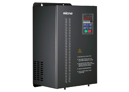
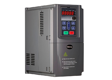
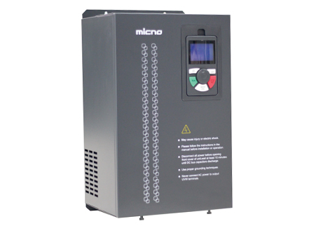
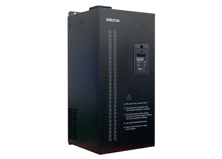
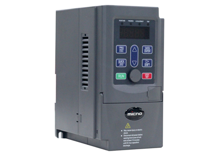
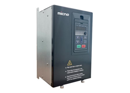
Three, Mykano KE300A-10 inverter features
KE300A-10 software is mainly optimized for water tank type double frequency drawing machine and direct feed type drawing machine tension control, the roll diameter calculation has been eliminated, and the user can carry out individual PID or main + PID way for tension control according to the working conditions. (Individual PID control is only supported for winding applications)
Several groups of parameter macros are set according to different user habits to minimize the user's workload of setting parameters.
FP-01 function parameter value 5-Restore to winding parameter 1 (separate PID control, automatic reset of fault, PID detection of the broken line is effective)
FP-01 function parameter value 6-Restore to payoff parameter 1 (automatic reset of fault)
FP-01 function parameter value 7-Restore to winding parameter 2 (default main + PID control)
FP-01 Function parameter value 8-Restore to payoff parameter 2
FP-01 function parameter value 9-Restore to direct wire drawing machine for parameters.
(1), easy to install, simple equipment debugging: only need to correctly adjust the position of the tension detection potentiometer, turn on the machine can automatically track the speed of the draw
degree, without other external signal control, directly constitutes an independent whole, saving equipment costs.
(2), regardless of thick wire, thin wire, regardless of high speed, or low speed, tension is always constant, only determined by the counterweight of the tension dynamic pulley.
(3), can be in the lower limit of the tension pendulum, the middle point of the zero position, or the upper limit of the position of any position to start the operation.
(4), automatic identification of the speed of the take-up line, automatic tracking of the line speed of the take-up line, and the tension pendulum are basically maintained at the set midpoint position.
(5), modular design, very flexible configuration.
(6), high starting torque: no PG vector control mode, at 0.5Hz, can provide 150% starting torque.
(7), excellent robust performance, which can ensure that the load can start and stop quickly.
(8) Fast dynamic response: the dynamic response time is less than 20ms in the PG-free vector control mode;
(9), fast current limiting function: can quickly limit the current within the protection point, reducing the probability of frequent overcurrent alarm failure.
IV. System control scheme
The main circuit wiring is very simple, connect the three-phase power supply to the inverter input R, S and T terminals, and connect the inverter output U, V and W to the corresponding motor three-phase terminals. Pay attention to the terminal markings when wiring to prevent misconnection or reverse connection. Details are shown in the following diagram.

High-speed wire drawing machine wiring schematic
1, the control system to stretch the inverter switch signal, when the D1 end and COM end closed, then start the inverter, disconnected to stop the inverter.
When the D3 end is closed with the COM end, it also starts the inverter, and stops the inverter when it is disconnected.
2、When the stretching inverter starts to run, the output relay signal (T2A, T2C) is given to the winding inverter, that is, when the D1 end of the winding inverter is closed with the COM end, the inverter is started, and when it is disconnected, the inverter is stopped, so that the stretching transformer and the winding machine form synchronous control.
3, when the stretching inverter starts to run from 0HZ acceleration, its analog output signal (A01) sends out the corresponding 0-10V analog signal, do for the winding inverter given frequency. Make the stretching machine and winding machine to form a speed synchronization control.
4, the tension pendulum installed between the wire drawing machine out of the wire end and the wire end, used to detect the tension of the output wire, as the tension signal of the wire drawing winding feedback into the winding inverter, that is, the winding inverter analog input AI1 connected to the pendulum position feedback signal (0 ~ 10V), the desired pendulum stable operation of the position point set as a PID given value. The system always compares the feedback signal with the given value during operation, and the PID controller automatically operates according to its difference value, then superimposes with the current synchronous speed of winding (analog AI2 input) to adjust the output frequency of the inverter, so as to control the speed of winding motor relative to the wire speed of the stretching machine to achieve synchronization, and at the same time, the wire tension is kept constant.
IV. Commissioning operation
1、Self-learning parameter setting
Because of the need to use no PG vector control, the inverter control performance is based on the accuracy of the motor model, so before running the motor for the first time, it is necessary to self-learning motor parameters: please try to let the motor and load completely disconnected (no-load operation), so that after self-learning, in no PG vector control performance is better.
Step 1: Restore PP-01 = 1 to factory value.
Step 2: Please enter the following parameters according to the motor nameplate parameters, other parameters please follow the factory parameters.
P1-01=XXX motor rated power P1-02=XXX motor rated voltage
P1-03=XXX motor rated current P1-04=XXX motor rated frequency
P1-05=XXXX motor rated speed
Step 3: Set the function parameter P1-37 to 2 (motor parameters fully self-learning), when the inverter P1-37 set to "2" to determine, the keyboard panel display "FUNE" said to enter the self-learning state, and then press the keyboard panel RUN key, the "RUN" indicator light on the keyboard panel indicates that it is in self-learning (the motor will rotate when P1-37 is set to "2"), when the "RUN" indicator light on the keyboard panel goes out, the keyboard shows "RUN". indicator on the keypad panel goes out and the keypad displays "50.00", it means the self-learning has been completed.
Ø If a fault is reported during the "full self-learning (P1-37=2)" process, then set the function parameter P1-37 to 1 (motor parameter static self-learning).
2、Parameter setting
KE300A-10 special inverter for wire drawing machine internal settings according to the habits of different users factory parameters, mainly for the take-up parameters, pay-off parameters. Note: The factory parameters only try to reduce the user's workload of setting parameters, the actual use of some parameters still need to be adjusted or set according to the use of demand. Specific parameter settings are as follows.
Ø Stretching inverter parameter setting
The main circuit wiring is very simple, connect the three-phase power supply to the inverter input R, S and T terminals, and connect the inverter output U, V and W to the corresponding motor three-phase terminals. When wiring, you should pay attention to the terminal markings to prevent misconnection or reverse connection. Details are shown in the following diagram.

 English
  français
  Español
  русский
  português
  العربية
  tiếng việt
  ไทย
ไทย  中文
中文


 About MICNO
  Applications
 Construction Machinery
 Textile Machine
 Company News