- 0755-21675210
- acdrive@micno.com.cn

2022-04-08
Abstract: This article mainly introduces the application of MICNO KE300A frequency converter in roving frame, briefly describes the characteristics of KE300A frequency converter, the specific requirements of roving frame for variable frequency drive and other related matters needing attention.
Key words: MICNO, frequency conversion speed regulation, roving frame, KE300A
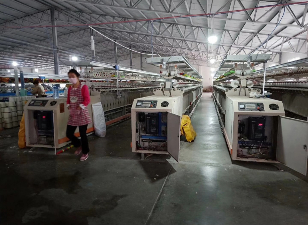
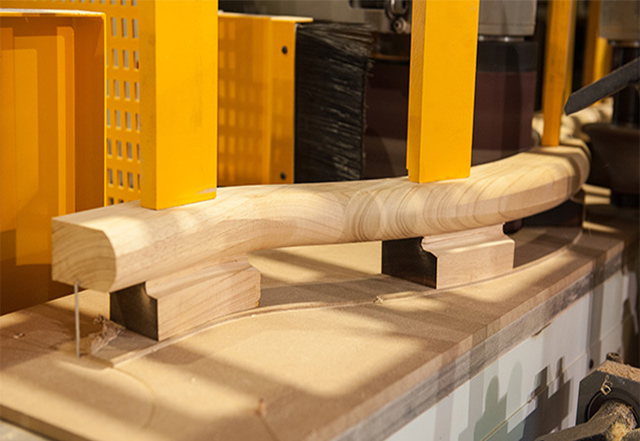
In the spinning technology, the roving process plays an important role. With the development of power electronic technology, PLC control, frequency conversion speed regulation, mechatronics and other technologies are used to replace the traditional mechanical structure, and the new type of suspended roving frame gradually replaces the traditional support spindle roving frame, so as to improve the reliability of the whole spinning machine, improve the spinning quality and automatic operation. Especially in recent years, the wide application of frequency conversion speed regulation technology in roving frame makes the roving frame have a broader development prospect.
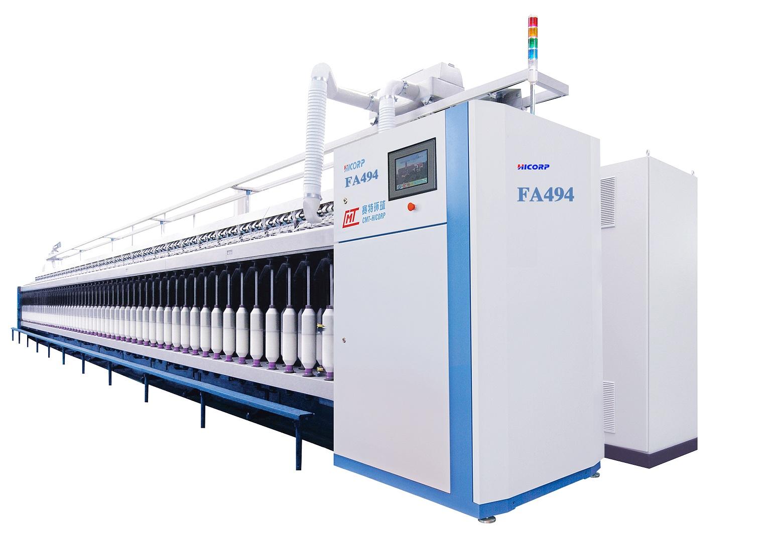
According to the requirements of the spinning process, after the roving frame draws the sliver by the roller, the yarn is drawn from the front roller for twisting, and then the yarn is wound on the bobbin according to the requirements of winding and forming. The speed of front roller drawing yarn is constant, and the winding speed is reduced in inverse proportion with the increase of the winding diameter. The traditional roving frame adopts a mechanical cone pulley speed change mechanism, and the belt moves on the upper and lower cone pulleys to change the winding and the lifting speed so as to complete the winding and forming of the roving. One of the factors affecting the quality of the yarn in the process of roving production is the details in the start and stop of machine and inching.
1. Roving frame driven by the single motor
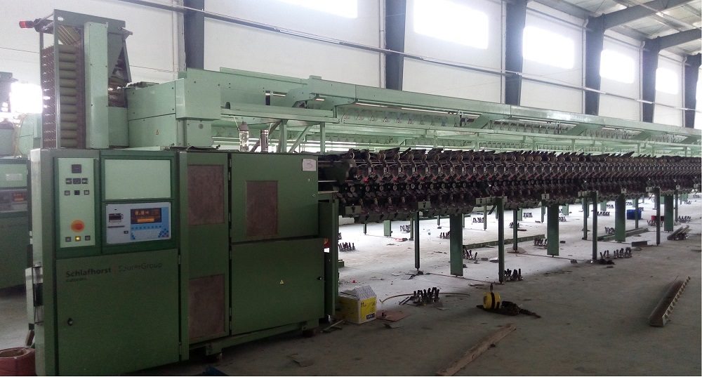
The main drive of the roving frame is driven by an AC asynchronous motor, in order to solve the problem of the breakage of the roving caused by too fast acceleration when the motor is started. In terms of quality problems such as uneven roving evenness during stop, the traditional solution is to install reactors, time relays and electromagnetic clutches, which are collectively referred to as "anti-detail devices". In addition, when the speed of the whole machine needs to be changed for spinning different varieties, the speed change is realized by manually replacing the pulley.
The application of frequency conversion technology can achieve smooth start well, eliminate the impact force during mechanical start, realize stepless speed regulation, meet the production technological requirements, and improve the yarn quality. The application of this technology does not need to change the teeth or pulleys when spinning different varieties, and the change of the technological speed of the equipment can be completed only by the frequency conversion setting, but the cone pulley speed change mechanism is still retained.
At present, the new type of roving frame and the old one use AC frequency conversion technology. So that this technological problem can be solved. Through the yarn quality test of the FA413 roving frame before and after the transformation, we know that the CV% of the roving evenness in the start-up section decreased by 2 to 3%, and the thickness and details of the roving decreased by more than 90%.
2. Roving frame driven by multiple motors
Due to the poor stability of the transmission speed of the mechanical cone pulley speed change mechanism, the operation is difficult, and the quality of the roving is likely to be unstable. Therefore, many manufacturers have launched new multi-motor-driven roving frames, canceling the cone pulley speed change mechanism, forming mechanism, differential mechanism, swing mechanism and reversing mechanism, etc., and also canceling the twist, lift, winding, tension, forming angle and other changing gear. 4 motors are used to drive the drafting roller (to generate drafting multiples), flyer (to wind the roving onto the bobbin), bobbin (to generate twist on the roving) and dragon tendon for lifting (to complete the winding shape). After using 4 electric motors to drive, in addition to simplifying the mechanical structure and canceling the above-mentioned gears, it also reduces noise, increases the speed, reduces roving ends, and increases the output of a single machine (the speed of the main engine is increased by more than 30%) to ensure stable roving quality and simple and fast technology.
However, the currently produced single-motor-driven roving frame still accounts for a large proportion, due to the low price. The multi-motor-driven roving frame has high speed and good performance, but its sales only account for about 10% due to its high price.
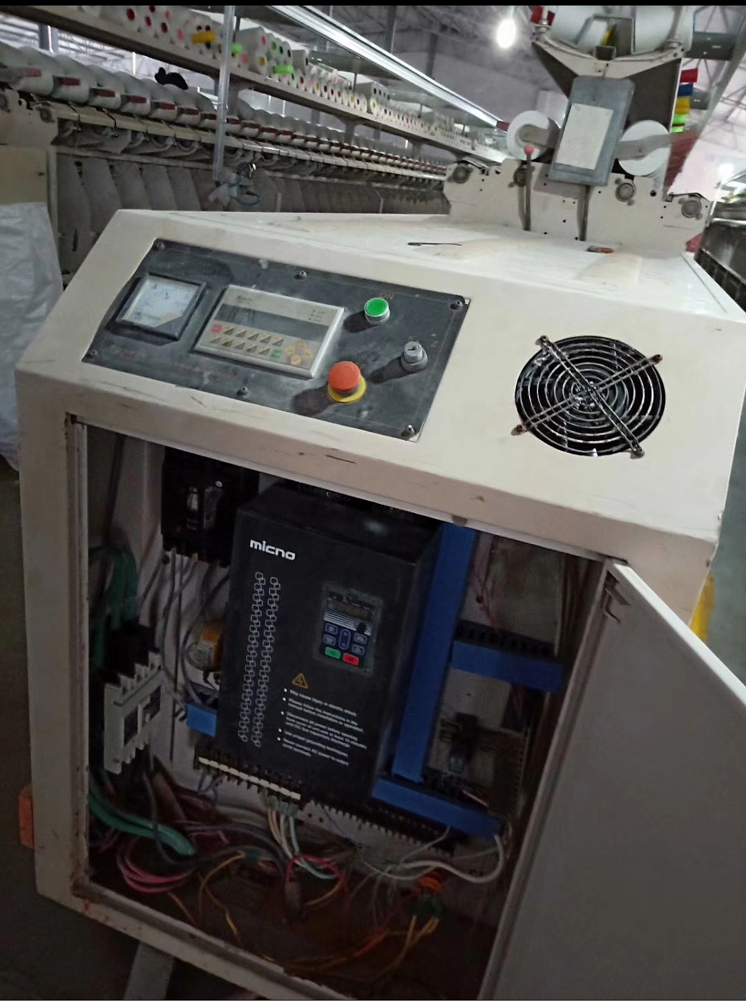
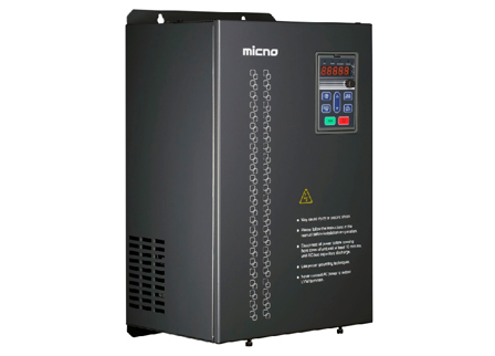
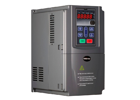
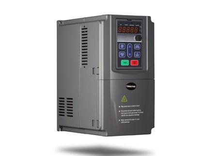
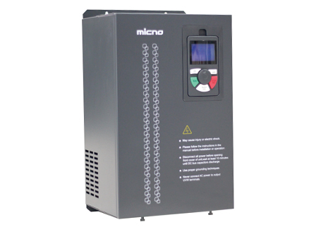
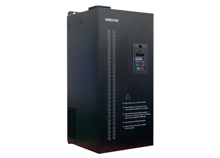
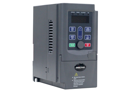
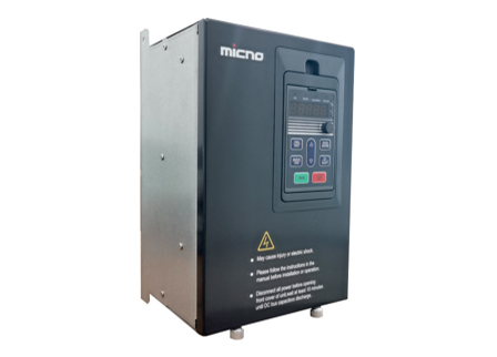
1. The characteristics of the MICNO KE300A frequency converter. The KE300A frequency converter has achieved high efficiency and low failure rate in the application of the suspended roving frame on site, and has been unanimously recognized by customers.
The advantages of the solution are summarized as follows:
(1) Smooth start and stop: slow acceleration, use the S-curve acceleration and deceleration function, and use the motor to start and stop softly and smoothly. Reduce the impact and wear of the machine and damage to the machine, and protect the mechanical equipment.
(2) Convenient speed regulation: the output frequency (speed) of the frequency converter can be adjusted through an external potentiometer, and there is no need to replace the speed change wheel of the machine. Different spinning speeds can be set according to different spinning processes, that is, the spinning speed can be set higher for small yarns, and appropriately reduced for large yarns, so as to exert the potential maximum production capacity of the roving frame.
(3) Support flyer positioning and parking function.
(4) No need to replace the pulley when changing the spinning variety. Just set the required rotate speed through the frequency converter.
(5) The starting current is small, which reduces the capacity of the power supply equipment and has a significant power saving effect.
2. System control scheme
The main circuit wiring is very simple. Connect the three-phase power supply to the input R, S, and T terminals of the frequency converter, and connect the output U, V, and W of the frequency converter to the three-phase terminals of the corresponding motor. When wiring, pay attention to the terminal identification to prevent misconnection or reverse connection. The details are shown in the figure below:
The above figures only list the common control wiring configurations. If you need to implement complex functions, please refer to the manual to modify the relevant wiring loops and terminal function definitions. Since the KE300A is a standard model, most parameters can be set according to the factory parameters. When using it, users do not need to do too many complicated settings, and only need to modify the simple parameters according to the actual use site.
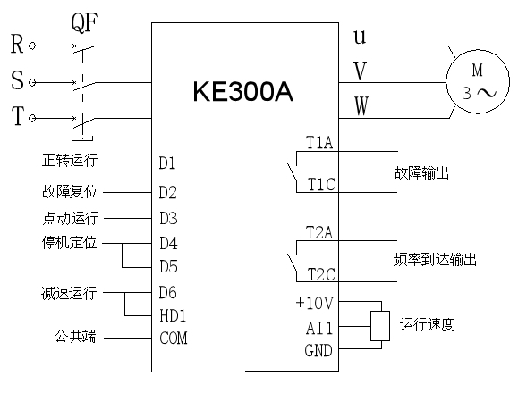
Running forward Fault output
Failure reset Frequency arrival output
Inching operation Operation speed
Stop positioning
Slow running
Common port
The application of (MICNO) KE300A frequency converter in the roving frame actually solves the problems existing in the roving production process. And after adopting it for control, the system control is simpler, and the control system has multiple protections, making the system more secure and reliable. Ordinary roving frames such as FA421, FA423, TJFA458, etc. all adopt frequency conversion speed regulation technology.
The application of frequency conversion speed regulation technology in the roving frame is necessary, and it is also feasible to popularize and apply it on the traditional roving frame equipment. With the development of microelectronics technology and power electronic technology, the development of frequency conversion speed regulation technology has also advanced by leaps and bounds. Today, the adoption of frequency conversion speed regulation technology directly promotes the rapid development of the mechanical structure of the roving frame, which has laid a solid foundation for the high speed, high quality and high intelligence of roving frame. It can be said that without the development of frequency conversion speed regulation technology, there will be no high-quality roving frame today. The higher and higher level of mechatronics of roving frame will be the future development direction.
 English
  français
  Español
  русский
  português
  العربية
  tiếng việt
  ไทย
ไทย  中文
中文

 About MICNO
  Applications
 Construction Machinery

 Textile Machine
 Company News