- 0755-21675210
- acdrive@micno.com.cn

2022-01-17
In the paper production process, rewinding is the last process of web production. It is a mechanical equipment used for quality inspection. It rewinds the printed material to find defective products. When the defective product is found, it is artificially pressed and remembered. The system will automatically slow down and stop, turn around and slowly search for defective products and stop manually for cutting. The rewinder is a key part of forming the quality of the finished paper roll.
1. Structure of rewinder
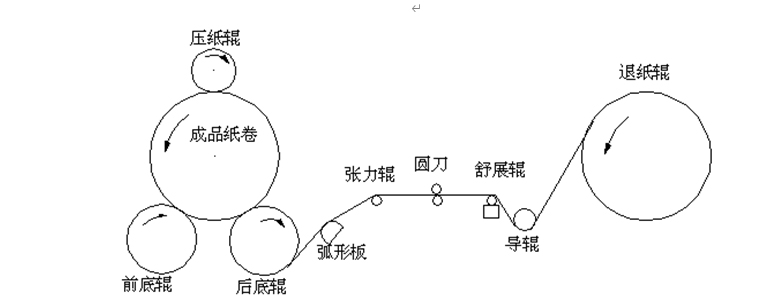
The structure of the rewinder can be divided into four major parts: the unwinding part, the slitting part, the rewinding part, and the unloading table.
The rewinding section is composed of a front bottom roller, a rear bottom roller, and a pressure roller. The front and rear bottom rollers are respectively controlled by a frequency converter, and the pressure roller is controlled by a hydraulic control system.
The unwinding part is also equipped with a separate motor, which is controlled by a frequency converter. In order to precisely control the tension, it is also equipped with a tension sensor or a regulating roller.
The slitting section is composed of several round knives that can be pneumatically controlled. Each round knife is controlled by a motor. The speed of the round knife motor is generally about 10% to 20% faster than the speed of the paper.
The function of the unloading table is to unload the paper from the two bottom rollers, separate the paper roll, and then use the conveyor chain to send it to the packaging department. The modern paper unloading table mostly adopts hydraulic control, which is the reason why the pressure roller is also more and more hydraulically controlled: First, it is convenient to use a hydraulic pump; second, the control accuracy is high.

Figure 1: Structure diagram of rewinder
(压纸辊:pressure roller 成品纸卷:finished roll 前底辊:front bottom roller 后底辊:rear bottom roller 弧形板:Arc panel 张力辊:Tension roller 圆刀:circular knife 舒展辊:spreader roll 导辊:running roller 退纸辊:Unloading roller)
2. Rewinding machine control requirements
The quality index of the finished paper roll is: it has enough hardness, and the inner tightness is loose, and the radial hardness is evenly distributed, so as to ensure that the paper roll is not deformed or cracked during transportation and storage, and it can run smoothly on the processing equipment. Therefore, different paper grades have different quality indicators for the rewinding finished paper rolls, so they have different requirements for the automatic control system of the rewinding machine.
In the rewinding process, the paper web is drawn from the unwinding roll, bypasses the paper guide roller and the spreading roller, and is fed through the slitting mechanism at a fixed position from under the machine to bypass the back bottom roller, and then is wound on On the reel, as shown in Figure 1:
(1) Control requirements for the ejection roller
The main control requirement of the unwinding roller is to control the tension, there is a certain static tension before running, and in the production, according to the quality of the parent roll, the rewinding tension should be appropriately increased and reduced to reduce the rate of breakage of the paper web.
(2) Front and rear bottom roller control requirements
The front and rear bottom rollers are the main producers of rewinding force. When there is a torque difference between the two bottom rollers, the rewinding force is produced, and the requirement is gradually reduced as the diameter of the paper roll increases. The size of the rewinding force determines the tightness of the paper roll, and increasing the rewinding force can increase the tightness of the paper roll. During the acceleration process, it is necessary to increase the rewinding force to compensate for the slack of the paper caused by the acceleration. During the deceleration process, it is necessary to reduce the rewinding force to reduce the impact of the tightening of the sheet caused by braking.
In production, under normal circumstances, the rewinding force is automatically controlled according to the preset rewinding force curve, and the operator does not need to change it, and the predetermined effect of tensioning the paper roll can be achieved.
(3) Control requirements for the pressure roller
The function of the pressure roller is to keep the positive pressure of the paper roll on the bottom roller constant during the rewinding process and to ensure the accuracy of the rewinding force. At the beginning of rewinding, it puts a lot of pressure on the paper roll. As the diameter of the paper roll becomes larger, the pressure it exerts on the paper roll gradually decreases. When the roll diameter reaches a certain value, the pressure provided by the platen roller The load is zero, at this time, it only exists as a device to maintain the position of the paper roll. The platen roller is equipped with a position measuring device, which can provide the position of the platen roller and the diameter of the paper roll. As the diameter of the paper roll increases, the pressure of the platen roller will change along the set program curve. The pressure control program of the platen roller must be selected according to the quality of the paper and the final diameter. Like the control of the bottom roller, the pressure of the platen roller is automatically controlled according to the pre-set pressure curve, and the operator does not need to change it.
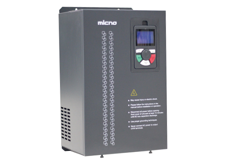
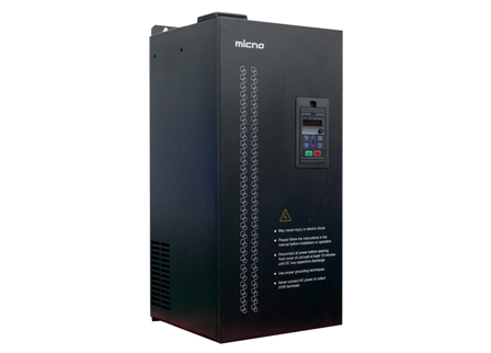
1. Inverter selection
According to the motor parameters of the front bottom roller, front bottom roller, and unloading roller of the on-site rewinder, the recommended inverter models are as follows.
| Name | Motor rated power | Frequency converter model | Rated power | Rated voltage | Rated output current | Quantity | Remark |
| Front bottom roller | 45kW | KE600-110G-T4 | 110KW | 3AC 380V | 210A | 1 | Configure braking unit and braking resistor |
| Front bottom roller | 45kW | ||||||
| Unloading roller | 55kW | KE600-055G-T4 | 55KW | 3AC 380V | 110A | 1 |
2. Control method
(压纸辊:pressure roller 成品纸卷:finished roll 前底辊:front bottom roller 后底辊:rear bottom roller 弧形板:Arc panel 张力辊:Tension roller 圆刀:circular knife 舒展辊:spreader roll 导辊:running roller 退纸辊:Unloading roller)
(1) Bottom roller control plan
The front bottom roller and the rear bottom roller of the on-site rewinder are composed of two motors, which control the rewinding. A frequency converter is used for synchronous control. During the working process, the front bottom roller and the rear bottom roller are always controlled at a constant speed. In order to improve the control accuracy, an encoder is installed on one of the motors for closed-loop vector control. The PLC system provides speed control signals, start-stop signals (synchronized with the inverter of the paper ejection roller), and forward and reverse jog signals to the inverter for control. The speed control signal must gradually increase according to the diameter of the paper roll, and the signal gradually decreases, that is, the speed of the front bottom roller and the rear bottom roller must gradually decelerate as the diameter of the roll gradually increases. The principle of the bottom roller speed control is the same as the pressure control principle of the platen roller. Due to the need to stop quickly, it is necessary to increase the braking unit and braking resistor (all resistors are connected in parallel). See the picture above for details.
(2) The control scheme of the ejection roller
The unwinding roller of the on-site rewinder is composed of a motor to control the unwinding, and a frequency converter is used for constant speed (tension) control. In order to improve the control accuracy, an encoder is installed on the motor for closed-loop vector control. The PLC system controls the inverter with start-stop signals (synchronized with the bottom roller inverter), forward and reverse jog signals, etc. The constant speed (tension) control of the unwinding roller adopts the tension change of the on-site tension roller and feeds it back to the PID control system of the inverter, that is, the inverter analog input AI1 is connected to the tension roller feedback signal (4-20mA). The tension stability value is set to the PID given value. During the operation of the inverter, the feedback signal is always compared with the given value, and the PID controller automatically calculates according to the difference.
It is superimposed with the current synchronous speed of the bottom roller inverter (analog AI2 input), and the output frequency of the inverter is changed to adjust the speed of the ejection roller motor to ensure the stability of the tension roller, thereby achieving constant tension control. Due to the need to stop quickly, it is necessary to increase the braking unit and braking resistor (all resistors are connected in parallel). See the picture above for details.
(3) Control scheme of pressure roller
The pressure roller is controlled by a pressure curve, the pressure output corresponding to the diameter of the paper roll is read from the pressure curve, and the hydraulic system valve is controlled by an electro-hydraulic proportional amplifier, so that the pressure of the paper roller on the paper roll follows the pressure curve.
The encoder is used to measure how much the diameter of the paper roll increases when the paper roll rotates one round, and the PLC system uses the following formula to calculate the pressure curve of the platen roller to obtain the pressure value that should be given.
Y=K÷R
Y: pressure of the platen roller (taper coefficient function), K: constant number of proportions R: diameter of the paper roll
3. Other instructions
(1) KE600 inverter only supports two PG cards, please refer to page 154 of KE600 manual for details.
| Name | Input type | Power supply | Whether to support frequency division output |
| OC PG card | Open collector signal | +15V | Yes |
| Differential PG card | Differential signal | +5V | Yes |
(2) Ensure that the encoder is installed coaxially with the motor. The encoder should use shielded wire, and the shielded wire should be grounded at the motor side. The wiring form of the PG card should correspond to the output mode of the encoder.
(3) Both inverters work in vector control mode, and the correct motor nameplate parameters must be input for self-learning.
1. Self-learning
Since PG vector control is required, the control performance of the inverter is based on the accuracy of the motor model. Therefore, before running the motor for the first time, it is necessary to self-learn the motor parameters: please try to completely disconnect the motor from the load (no-load operation) ), after such self-learning, vector control performance with PG is better.
(1) Set the function parameters P0-02=0 (keyboard operation), P0-01=2 (with PG vector control), and other parameters please follow the factory parameters.
(2) Set the function parameter PP-02=01, call out the UO parameter group, rotate the motor, and monitor whether the value of U0-14 (load speed display) changes, otherwise, the PG card wiring error.
(3) Then please input the following parameters according to the parameters on the motor nameplate:
P1-00= XX motor type selection P1-01=XXX motor rated power
P1-02 = XXX rated motor voltage P1-03 = XXX rated motor current
P1-04=XXX motor rated frequency P1-05=XXXX motor rated speed
P1-28 = XXX encoder line number P1-30 = 0 ABZ incremental encoder phase sequence
(4) If the motor is completely disconnected from the load, set the function parameter P1-11 to 2 (the motor parameters are fully self-learning). If the motor and the load cannot be disconnected, set the function parameter P1-11 to 1 (motor parameter static self-learning). Then press the RUN key on the keyboard panel, the inverter will automatically calculate the following parameters of the motor:
P1-06: Motor stator resistance P1-07: Motor rotor resistance
If adopting "motor parameter comprehensive self-learning", it will automatically calculate:
P1-08: Motor leakage inductance P1-09: Motor mutual inductance P1-10: Motor no-load current
When the inverter P1-11 is set to "2" or "1" after confirming, the keyboard panel displays "FUNE" to indicate that it has entered the self-learning state, and then press the RUN key on the keyboard panel, the "RUN" indicator on the keyboard panel is on, indicating During self-learning (the motor will rotate when P1-11 is set to "2"), when the "RUN" indicator on the keyboard panel is off and the keyboard panel displays "50.00", it means that the self-learning has been completed.
If an "E-20" fault is reported during self-learning, set P1-30 to 1 and perform self-learning again.
2. Set function parameters
When using, users do not need to do too many complicated settings, only need to make simple parameter modifications according to the actual use site. The specific parameter settings are as follows:
(1) Parameter setting of the bottom roller inverter
| Function code | Set value | Features |
| P0-01 | 2 | Control mode: PG vector control |
| P0-02 | 1 | Terminal command channel |
| P0-03 | 1 | Analog AI1 setting |
| P0-17 | 50 | Acceleration time (when the acceleration needs to be fast, reduce this parameter, if it is too small, it is easy to report fault protection). |
| P0-18 | 50 | Deceleration time (when the deceleration needs to be fast, reduce this parameter, if it is too small, it is easy to report fault protection). |
| P4-00 | 1 | D1 terminal function: forward running |
| P4-02 | 4 | D3 terminal function: forward jog |
| P4-03 | 5 | D4 terminal function: reverse jog |
| P4-13 | XXX | AI1 analog channel minimum input; when the PLC gives 0 revolutions, if the frequency of the inverter display is not 0, increase this parameter. If it is 4-20 mA, set 2V, corresponding to 4mA. Note: Jump the J1 jumper on the control board to the current position. |
| P4-15 | XXX | AI1 analog channel maximum input; when the actual speed does not reach the set speed, reduce this parameter, otherwise, enlarge this parameter. |
| P5-07 | 0 | AO1 analog output function selection |
(2) Parameter setting of the inverter for the ejection roller
| Function code | Set value | Features |
| P0-01 | 2 | Control mode: PG vector control |
| P0-02 | 1 | Terminal command channel |
| P0-03 | 8 | PID control setting |
| P0-04 | 3 | Analog AI2 setting |
| P0-07 | 01 | A+B main and auxiliary calculation results |
| P0-10 | 70 | Maximum output frequency (when the winder is running at 50HZ, the unwinder needs to run when the disk is empty) |
| P0-12 | 70 | Upper limit frequency |
| P0-17 | 1 | Acceleration time 1 |
| P0-18 | 1 | Deceleration time 1 |
| P4-00 | 1 | D1 terminal function: forward running |
| P4-02 | 4 | D3 terminal function: forward jog |
| P4-03 | 5 | D4 terminal function: reverse jog |
| P4-13 | XXXX | AI1 analog input minimum, |
| P4-15 | XXXX | AI1 analog maximum input, |
| P4-17 | 0.01 | AI1 filter time |
| P4-18 | XXXX | AI2 analog minimum input |
| P4-22 | 0.01 | AI2 filter time |
| P8-13 | 0 | Inversion control enable |
| P9-05 | 4 | Over churn gain |
| PA-01 | XXXX | PID keyboard setting |
| PA-05 | 5 | Proportional gain Kp1 |
| PA-06 | 1.8 | Integration time Ti1 |
| PA-08 | 50 | PID reverse cutoff frequency |
| PA-09 | 2 | PID deviation limit |
| PA-28 | 0 | PID stop calculation: stop without calculation |
| PP-02 | 01 | Call up U0 parameter group |
Ø Debugging process:
1.1. Set the function parameters, such as control mode, frequency setting mode, acceleration and deceleration time, etc.
1.2. When the tension roller is adjusted to the lower limit and the upper limit, the minimum voltage value of the feedback signal is used as the parameter setting value of P4-13, and the maximum voltage value of the feedback signal is used as the parameter setting value of P4-15;
1.3. Adjust the tension roller to the midpoint position (the position is adjustable), and call out the U0-16 (PID feedback) monitoring parameter as the PA-01 parameter setting value;
1.4. Power-on operation, if the dynamic response of the tension roller is slow to the midpoint position, increase the proportional gain and reduce the integral time. The recommended adjustment method is: first increase the PA-05 proportional gain to ensure that the system does not oscillate; then decrease PA-06 integration time
2. PID parameter debugging guidance
2.1, the general steps of PID parameter setting
Ø Determine the proportional gain P (PA-05)
To determine the proportional gain P, first set the integral (PA-06=0) and differential (PA-07=0) of the PID, so that the PID is purely proportional. Gradually increase the proportional gain P from 0 until the system oscillates; then, in turn, the proportional gain P gradually decreases from this time until the system oscillation disappears. Record the proportional gain P at this time and set the PID proportional gain P as the current 60%~70% of the value. The adjustment of the proportional gain P (PA-05) is completed.
Ø Determine the integration time Ti (PA-06)
After the proportional gain P is determined, set a larger initial value of the integral interval Ti(, and then gradually reduce Ti until the system oscillates, and then in turn, gradually increase Ti until the system oscillation disappears. Record this Set the integral time constant Ti of PID to 150%~180% of the current value. The debugging of integral time constant Ti is completed.
Ø Determine the differential time Td (PA-07)
Differential time Td-generally don't need to be set, just set to 0. To set, use the same method to determine P and Ti, and take 30% when there is no oscillation.
 English
  français
  Español
  русский
  português
  العربية
  tiếng việt
  ไทย
ไทย  中文
中文


 About MICNO
  Applications
 Construction Machinery

 Textile Machine
 Company News