- 0755-21675213
- acdrive@micno.com.cn

2021-09-15
Ⅰ. Overview
Centrifugal dehydrators are widely used in the textile industry for dyeing and finishing, washing, weaving, and dewatering of washed materials in places such as hotels. The following is a brief introduction to the use of KE300A frequency converters on sliding-supported centrifugal dehydrators in Taizhou, Jiangsu.
The dehydrator is mainly composed of sliding support components, housing components, cone drum components, drive motors, etc. The shaft of the motor is connected with the cone. When the motor shaft rotates, the textile with water is in the cone drum. Due to the centrifugal force, the water of the textile is thrown to the outer wall of the drum, and drained from the underground drainage channel through the bottom plate through the drainage hole on the drum wall to achieve the purpose of dehydration. The whole machine is supported on three sliding support seats, and is equipped with a vibration amplitude control device. If the textile is placed unbalanced in the cone drum, it can be automatically controlled by this device. When the amplitude of the cone exceeds a certain value during operation, the power supply of the host will be cut off, so that the machine will stop working, and finally safety protection can be ensured.
The workflow is divided into 3 parts:
(1) Cloth feeding method: The textile with water enters into the cone drum from the doffing frame. At this time, the dehydrator runs at a low speed in the forward direction to ensure that the stacking adjustment of the textile can be carried out manually.
(2) Dewatering method: the textile with water is dewatered under the action of the high-speed centrifugal force of the cone drum. At this time, the dehydrator is gradually accelerated from a low speed, and finally runs at a high speed, and then after the set dewatering time is over, it will gradually decelerate until the operation stops.
(3) Cloth discharging method: the dewatered textile is transported from the cone drum to the car with finished products through the doffing frame, and at this time the dehydrator runs in the reverse direction at a low speed.
Ⅱ. Frequency conversion control system
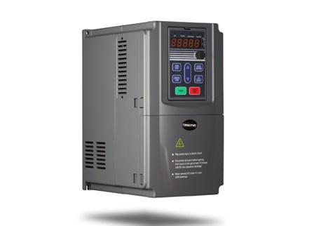
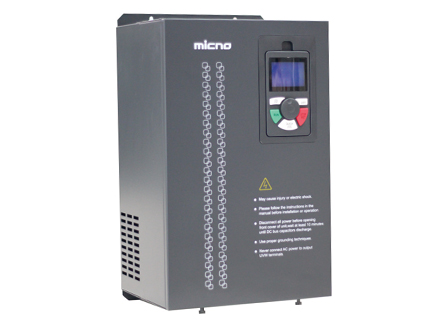
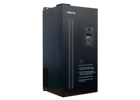
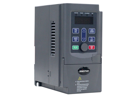
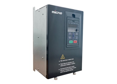
The centrifugal dehydrator belongs to the load of large inertia and approximate constant torque. It is necessary to configure the brake unit and brake resistor on the basis of the frequency converter to meet the requirements of the system. Choose the KE300A frequency converter, and its wiring main circuit and control circuit are shown in the figure:
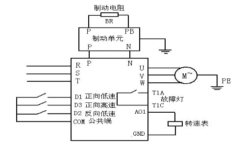
In the peripheral circuit of the frequency converter, there are mainly three parts:
(1) The P and N ends of the DC bus are connected to the P and N ends of the brake unit, and then the P and PB ends of the brake unit are connected to the control resistor BR.
(2) In the input terminal of control circuit, D1 is a positive low-speed signal, D3 is a positive high-speed signal, and D2 is a reverse low-speed signal.
(3) Among the output terminals of the control circuit, T1A and T1C are the fault indications of the frequency converter, and an external fault light is connected, and AO1 and GND are connected to an external 0-10V DC digital display (indication of frequency or rotate speed).
The braking characteristics of the dehydrator must include a brake unit and a brake resistor.
The installation and wiring of the brake unit must pay attention to: the temperature, humidity, corrosion, ventilation, etc. of the installation environment must meet the requirements of the instruction book. When connecting with the frequency converter, try to choose different colors of wires to prevent P/N connection, otherwise the brake unit will be burned and the frequency converter will be damaged. In terms of P and N wiring, 600V withstand voltage grade electric wires should be adopted, and the wiring length should be as short as possible. If the length exceeds 5m, twisted pair wires are required.
(1) The action of the brake unit:
The connection position of the brake unit in the system is as shown in the figure:
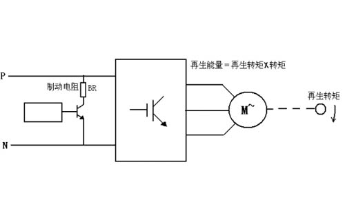
The action process of the power switch of the brake unit: ① When the motor is decelerating, the motor runs in a state of power generation to generate regenerative energy. When the motor is in the power generation state, the three-phase alternating current generated by it is rectified by the full bridge composed of six freewheeling diodes in the frequency converter part, which increases the DC voltage of the DC intermediate link in the frequency converter. ② When the DC voltage reaches the state where the brake unit is turned on (ON), the power switch tube of the brake unit is turned on, and the current flows through the brake resistor. ③ The brake resistor emits heat and absorbs the regenerative energy. The speed of the motor decreases and the voltage on the DC side decreases. ④ The voltage on the DC side is reduced to the value that makes the brake unit turn off (OFF), and when the power switch of the brake unit is turned off, there is no current flows through the brake resistor. ⑤ The motor continues to decelerate and the DC voltage rises again. ⑥ When the voltage on the DC side is high enough to make the brake unit work again, the brake unit repeats the above switching (ON/OFF) process to balance the DC voltage and make the system operate normally. When the regenerative energy is large, the switching (ON/OFF) frequency of the regenerative brake unit increases, which increases the brake torque, and the amount of electrical energy converted into heat energy per unit time increases.
Selection of dynamic resistance: In the work of the brake unit, the voltage rise and fall of the DC bus depends on the constant RC, in which R is the resistance value of the brake resistor, and C is the capacity of the electrolytic capacitor of the frequency converter. Known from the charge and discharge curve, the smaller the RC, the faster the discharge speed of the bus voltage is, and the smaller R is when C is kept constant in the frequency converter, the faster the discharge speed of the bus voltage is. Usually the resistance of the brake resistor is required to figure out
.
R=Uc2/[0.1047*(Tb-0.2Tm)N]Ω
In the formula: Uc brake unit operating voltage value is generally 710V/660
Tb brake torque
Tm motor rated torque
The brake resistor of this system is adapted to the normal braking of the automatic dehydrator, taking into account factors such as the wiring distribution, the distribution of the resistance of the resistor itself, and the temperature distribution of the resistor. There should be margin when selecting the resistance. In general, it is more appropriate to choose 1.2 times, that is, the resistance value R is 1.2 times R (calculated bit).
2. The function of over-voltage speed loss prevention:
During the decelerating operation of the frequency converter, due to the influence of load inertia, the actual rate of decrease of the motor speed may be lower than the rate of decrease of the output frequency. At this time, the motor will feed back electrical energy to the frequency converter, causing the voltage of frequency converter DC bus to increase. When it reaches 660V, the brake unit will act. Due to the certain utilization rate of the brake unit, if the influence of high inertia continues, the DC bus voltage will continue to rise. Using the over-voltage stall prevention function, the over-voltage stall point can be automatically compared with the actual DC bus voltage during the deceleration operation. If the latter exceeds the former, the output power of the frequency converter will stop decreasing, until it is detected that the latter is lower than the former, then the frequency converter will operate while the output power of it is decelerating.
3. Acceleration and deceleration time:
Due to the influence of load inertia, the acceleration and deceleration time of the motor speed must be set to a reasonable value. If the time is too short, faults such as over-current and over-voltage of the frequency converter will occur. If the time is too long, the operating power of the equipment will be greatly reduced.
Ⅲ. Concluding remarks
The centrifugal dehydrator has been successfully applied in the market. Its excellent performance and perfect protection measures have further improved the performance of the whole equipment of the centrifugal dehydrator. There are brake units inside the KE300A frequency converter below 22KW, which reduce the investment of users, save cabinet space and increase the market competitiveness of this type of frequency converter.
 English
  français
  Español
  русский
  português
  العربية
  tiếng việt
  ไทย
ไทย  中文
中文


 About MICNO
  Applications
 Construction Machinery

 Textile Machine
 Company News