- 0755-21675213
- acdrive@micno.com.cn

2021-12-09
Abstract
Discuss the transformation and application of high-voltage frequency conversion speed control system in the flue gas purification system of electrolytic aluminum plant. The on-site operation of the frequency converter shows that if the aluminum plant flue gas purification system adopts frequency converter to adjust the speed and save energy, the transformation is successful and the energy saving effect is obvious.
Keywords: high voltage frequency converter, aluminum plant flue gas purification system, energy saving
With the implementation of the national macro-control policies, the government has paid more and more attention to the clean production and energy-saving production of various high-energy-consuming enterprises, and has formulated energy-saving and consumption-reducing indicators. The aluminum smelting industry is the most power-consuming industry. As the country's energy-saving and emission-reduction policies increase and energy sources are becoming increasingly scarce, various aluminum plants are facing urgent pressure to save energy and reduce consumption.
The flue gas emitted during the aluminum electrolysis process includes gaseous matter and solid matter. Anode gas is produced during aluminum electrolysis. It contains H2F2, SiF4, CF4, CO2, etc., as well as pitch volatiles and various dusts, which harm the surrounding environment of the electrolysis plant and threaten the health of the operators. Therefore, the flue gas of the aluminum plant should be reasonably processed.
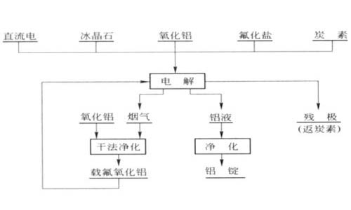
直流电direct current 冰晶石 cryolite 氧化铝aluminum oxide 氟化盐fluoride salt 炭素carbon
电解electrolysis
氧化铝aluminum oxide 烟气flue gas 铝液 molten aluminum 残极(返炭素)residual pole (return carbon)
干法净化dry purification 净化purification
载氟氧化铝fluoride-carrying aluminum oxide 铝锭aluminium ingot
Flow chart of the production of modern aluminum electrolysis industry
1. Introduction to the flue gas purification system
There are two ways to purify the flue gas produced in electrolytic aluminum plants in China: one is to use the method of dry purification, and the other is to use the method of wet purification. Wet purification was the main method of purifying flue gas in aluminum plants in the 1970s. Although this method purifies the flue gas, it also produces waste water, which also needs to be purified and requires a large investment and high operating costs. With the development of production, electrolytic aluminum plants in China are all developing in the direction of large-scale pre-baked tanks, all of which use the method of dry purification. Dry purification is to use the raw material aluminum oxide of the aluminum electrolytic cell as an absorbent to absorb the HF gas in the flue gas and intercept the dust in the flue gas. The aluminum oxide that has absorbed hydrogen fluoride is added to the electrolytic cell as a raw material. The dry purification method has a short process flow, simple equipment, high purification efficiency, and the trapped fluorine is returned to the electrolytic cell, saving a fluorine salt, and is widely used in large-scale pre-baked electrolytic cells.
2. Process introduction
After the electrolysis reaction of the electrolytic cell, the flue gas dust is generated. Under the negative pressure of the centrifugal boiler fan (hereinafter referred to as the fume extractor), the flue gas passes through the VRI reaction chamber under the bag house for adsorption reaction. And gas-solid separation of the flue gas is achieved with the cloth bag. Then the flue gas is discharged into the large chimney using a fume extractor to complete the process of flue gas purification.
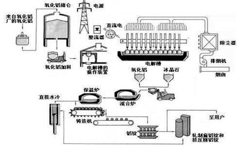
来自氧化铝厂的氧化铝aluminum oxide from aluminum oxide plant 氧化铝储仑aluminum oxide storage 氧化铝加料 aluminum oxide charging 电源 power supply整流器 rectifier 直流电 DC power 电解槽的操纵装置electrolyzer control device 电解槽electrolyzer 除尘器dust collector 排烟机fume extractor 烟囱chimney
直接水冷 direct water cooling保温炉holding furnace 混合炉mixing furnace 氧化铝 aluminum oxide冰晶石cryolite 铸造机 casting machine 铝锭 aluminum ingot 至用户 to users轧制扁铝锭和挤压圆铝锭rolling flat aluminum ingots and extruded round aluminum ingots
The purifying fume extractor is the key equipment of the flue gas purification system of the electrolysis workshop, and it is the guarantee of whether the flue gas can be effectively purified and the fluoride salt can be effectively recovered. The existing fume extractor system mainly has the following problems in the operation process.
(1) The design flow margin is too large, and the existing control method is that regardless of the production demand, the fan runs at the rated power (rotate speed), and the air volume adjustment adopts the inlet multi-leaf control valve, which results in a large amount of electrical energy waste.
(2) The starting current is too large, the water resistance soft start method is adopted. The starting current is relatively large, which not only causes a huge impact on the power grid, but also causes certain damage to the motor body structure and the fan bearing box. At the same time, the power side switch of the motor may be damaged, and sometimes even the power distribution circuit will trip, causing the entire purification system to lose power and stop operation, which seriously affect the normal operation of production.
(3) The protection system is simple. Only the overcurrent protector protects the equipment from overcurrent, and the safety and reliability of the equipment operation is low.
(4) The system cannot guarantee the operation of the constant pressure system. Because the speed of the fume extractor cannot be adjusted, the pressure of the system cannot be adjusted, and the relevant parameters cannot be effectively controlled, which has a great impact on the purification efficiency of the purification system.
3. Requirements for high-voltage frequency converters
The fume extractor is the power center of the flue gas purification system. Once the fume extractor fails to operate normally, it will not only affect production, cause huge economic losses, and may also threaten the personal safety of on-site production personnel; in addition, the working environment of the speed control system is relatively bad; at the same time, the flue gas purification system periodically beats to collect aluminum powder. Therefore, the high-pressure speed control system matched with the fume extractor requires extremely high reliability. Based on the above working characteristics, the main requirements for the frequency conversion speed control system are as follows:
(1) The frequency converter is required to have high reliability and long-term operation without failure;
(2) The frequency converter is required to have a bypass function. Once a fault occurs, the motor can be switched to power frequency operation;
(3) The speed control range should be large and the efficiency should be high;
(4) There is a resonance point jump setting, which can make the motor run away from the resonance point and prevent the fan from surging.
(1) Drag the equipment
The flue gas purification system of the second electrolysis workshop of an aluminum factory in Shandong is designed to be driven by 8 three-phase high-voltage asynchronous motors. Its parameters are: rated voltage of 10KV, rated power of 900KW, rated current of 65A, power factor of 0.86. Usually in daily production, 4 units (4 standby units) are put into operation so as to meet the needs of flue gas purification. The fans are connected in parallel through the flue, and the negative pressure of the purification system is adjusted by the opening and closing of the butterfly valves in each flue of fan, and the opening degree of the butterfly valves of each flue can only be judged and controlled based on the actual experience of the operator.
2. Technological transformation plan design
(1) The configuration of frequency converter
According to the rated parameters and actual operating conditions of the site, after research and discussion, it is determined that the modified equipment is equipped with the following frequency converters, and the main parameters are as follows:
| Serial number | Items | Parameters |
| 1 | The model of frequency converter | HE1000-0900G-T16 |
| 2 | Rated capacity | 900kVA |
| 3 | Rated voltage | 10KV |
| 4 | Rated current | 65A |
| 5 | Number of frequency converters | 4 |
| 6 | Drag mode | One frequency converter drags two fans and bypasses manually |
| Note | The high-voltage frequency converter with this configuration can only drive one fan for online operation, and the other fan can be used as a backup. | |
(2) Description of the switching mode of frequency converter
According to the rated parameters and actual operating conditions of the site, the switching control bypass system of the provided HE1000 series frequency converter adopts the scheme that one frequency converter drags two fans and bypasses manually, and the principle of the electrical main circuit is shown in the following figure:
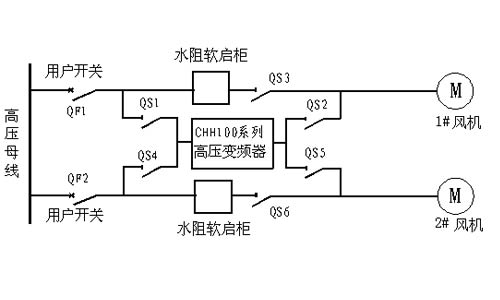
高压母线high voltage bus 用户开关user switch 水阻软启柜water resistance soft-start cabinet 风机fan 高压变频器 high voltage frequency converter
The diagram of one to two manual switching bypass system of high voltage frequency converter
Ø The frequency converter is composed of a user switch, a one-to-two manual switching bypass cabinet, HE1000 series high voltage frequency converter, and a high voltage motor.
Ø One-to-two manual switching bypass cabinet is composed of six switch gates QS1, QS2, QS3, QS4, QS5, and QS6.
Ø The cabinet is designed in strict accordance with the "five prevention" interlocking requirements, which can fully guarantee the safe operation of the frequency conversion speed control system.
QS3 and QS2 have interlocking function and cannot be closed at the same time;
QS6 and QS5 have interlocking function and cannot be closed at the same time;
QS1, QS2 and QS4, QS5 have interlocking function and cannot be closed at the same time;
Ø With the above main circuit scheme, the following operation modes can be realized:
⑴ 1# fan frequency converter is operating: it is composed of QF1, QS1, QS2, and QS6. Among them, QS6 is used to quickly close the bypass for 2# fan for standby.
⑵ 1# fan power frequency is operating: it is composed of QF1, QS3.
⑶ 2# fan frequency converter is operating: it is composed of QF2, QS4, QS5, QS3. Among them, QS3 is used to quickly close the bypass for 1# fan for standby.
⑷ 2# fan power frequency is operating: it is composed of QF2, QS6.
Ø When the frequency converter fails during operation, the fault switching valve signal is sent to the superior user and the switch trips. Because the frequency conversion bypass switch of the standby fan is closed, with the original control system user quickly starts the standby fan to run. Because the frequency conversion fan stops, the amount of smoke absorbed will decrease under the action of inertia, and the standby fan will be quickly started. The valve is controlled to adjust the flow through the original control system to ensure normal operation of production.
(3) Control mode of the frequency converter
Manually switch and drag the corresponding load through the manual switch bypass cabinet of the frequency converter, and use the on-site remote operation box platform to start and stop the frequency converter, and adjust the rotate speed of motor. The operation box is installed directly on the remote monitoring room. This solution is convenient for transformation and does not need to modify the original control system. It only needs to fully open the valve that controls the fan, and adjust the rotate speed of motor through the operation box platform to control the flow.
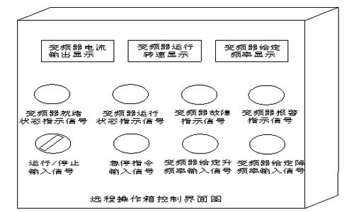
变频器电流输出显示 frequency converter current output display变频器运行转速显示frequency converter running rotate speed display 变频器给定频率显示frequency converter given frequency display
变频器就绪状态指示信号frequency converter ready state indication signal 变频器运行状态指示信号frequency converter running state indication signal 变频器故障指示信号frequency converter fault indication signal 变频器报警指示信号frequency converter alarm indication signal 运行/停止输入信号run/stop input signal 急停指令输入信号emergency stop command input signal 变频器给定升频率输入信号frequency converter given frequency up input signal 变频器给定降频率输入信号frequency converter given frequency down input signal
The control interface diagram of remote control box
Control circuit configuration diagram
(4) Frequency control mode of frequency converter
Send output current, output frequency and other signals of the frequency converter to the remote monitoring room. The electrician on duty determines the amount of flue gas in the flue gas purification system, and manually adjusts the frequency given signal through the remote control operation box, so as to meet the requirements on flow and pressure for the fan.
Features: The manual adjustment method does not need to detect on-site control signals, and the control is simple. According to the flow (pressure) required on the site, combined with the relationship between the operating frequency and flow (pressure) of the frequency converter, the frequency of the frequency converter can be adjusted. It is generally applicable to the working condition with little change in production capacity, relatively stable field operation frequency and no need for frequent adjustment.
(1) Time measurement effect
In order to evaluate the effect of the frequency conversion transformation on the purification fume extractor system, the situation of actual use and power saving of the equipment is measured and data is analyzed one month after the system was put into normal operation.
Since the entire flue gas purification system of the second electrolysis workshop is usually put into operation in daily production, 4 sets (4 spares) can meet the needs of flue gas purification, and the load change of each fan is basically the same, that is, the power consumption of each frequency converter is basically the same. Now a variable frequency fan is randomly selected on a normal production day, and the system is switched to power frequency operation. The baffle is used to control the air volume. The measurement data on the spot is as follows:
| Adjustment method | Input current | Input voltage | Input power factor |
| Valve adjustment | 52A | 9970V | 0.84 |
| Frequency conversion adjustment | 31.2A | 9972V | 0.96 |
The test results:
(1) Calculation of power consumption under the power frequency state of the motor:
Calculation formula: (KW) = 1.732×U×I×cosφ÷1000
Motor power consumption: =1.732×U×I×cosφ÷1000= 1.732×9970×52×0.84÷1000
=754.26 kW
(2) Calculation of power consumption under variable frequency status:
Calculation formula: (KW) = 1.732×U×I×cosφ÷1000
Motor power consumption: = 1.732×U×I×cosφ÷1000= 1.732×9972×31.2×0.96÷1000
=517.31kW
2. Energy-saving benefits:
The comparison of energy saving benefits between the valve adjustment and the frequency conversion adjustment of the purifying fume extractor is as follows:
| Items | Single purifying fume extractor | 4 purifying fume extractors |
| Total power saving rate | ×100%=(754.26-517.31) ÷754.26×100%=31.41% | 31.41% |
| Annual savings of electricity | the annual amount of electricity saving= the electricity consumption before the transformation × the energy saving rate × the operating time ÷ 10000 =754.26×31.41%×300×24÷10000=1.705 million kWh | 682.28 million kWh |
| Annual savings of electric charge | the annual amount of energy-saving benefit = annual electricity saving after transformation × unit price of electricity = 1,705,700 kWh×0.47 yuan/kWh = 801,600 yuan | 3.2064 million yuan |
| Annual savings of standard coal | Annual electricity saving amount is converted into standard coal = annual electricity saving × 0.366g standard coal/kwh =1.705 million kWh×0.366g standard coal/kwh=624.28 tons | 2497.12 tons |
| Note: 1. The electricity price is 0.47 yuan/kWh, and the annual operating time is operating days 300×24 hours. | ||
3. Other benefits
u Thanks to the frequency conversion control system, the air volume can be accurately controlled, and compared with the valve control, it is more intuitive and convenient to adjust the air volume of the fan to meet the production needs;
u Thanks to the use of frequency conversion technology, the motor realizes soft start, and there is no starting current impact; it reduces the impact of the instant increase of the outlet pressure of the fan on the fan, thereby prolonging the service life of the fan and other equipment;
u Since the rotate speed of fan is reduced to 75% of the original, the vibration frequency and noise of the fan duct are greatly reduced, and the mechanical life of the fan and motor bearings is prolonged;
u Since the bypass valve is almost inoperative, the vibration and wear and corrosion of the air duct are reduced, and the mechanical life is improved. After the SO2 temperature is lowered, the corrosion effect on the air duct and pipeline valves is reduced.
5. Energy saving suggestions
The equipment driven by the frequency converter needs to work in a good condition. According to our experience in previous cases, the aging of equipment, blockage of air ducts, and air leakage will seriously affect the energy-saving effect of the frequency converter. Therefore, it is necessary to regularly maintain the equipment, clean the obstruction, and manage the air leakage to make the frequency converter achieve the best energy-saving effect.
The frequency converter should be regularly maintained, and operators should be regularly assessed and trained to avoid failure of the frequency converter due to maintenance or operation errors, causing the equipment driven by the frequency converter to work under the power frequency state, which affects the overall energy saving effect.
It can be seen that after investing in four HE1000 series high voltage frequency converters produced by Shenzhen MICNO Electric Co., Ltd., electricity costs of about 2,396,400 yuan can be saved throughout the year. In addition, the power factor can reach more than 0.95, which is greater than the motor power factor of 0.89, reducing a lot of reactive power. In addition, the soft start of the motor can be realized, which can avoid the impact on the motor insulation caused by the impact of high current start, reduce the maintenance of the motor, save the maintenance cost, and greatly extend the service life of the motor. It reduces the labor intensity of the operating personnel and is well received by the operating personnel and maintenance personnel. After the purifying fume extractor machine is transformed by the frequency converter, the energy-saving effect is remarkable, and it meets the design requirements. The advancement and reliability of this series of frequency converters have been confirmed by many industrial applications.
References:
[1] Guidelines for energy-saving transformation of fans and pumps (edited by the Department of Comprehensive Utilization of Resources and Energy of the State Economic and Trade Commission).
[2] A guide to energy-saving technology of AC motor frequency conversion speed control system (edited by the Energy Conservation Information Communication Center of the State Economic and Trade Commission).
[3] HE1000 Series Instruction Manual
 English
  français
  Español
  русский
  português
  العربية
  tiếng việt
  ไทย
ไทย  中文
中文


 About MICNO
  Applications
 Construction Machinery

 Textile Machine
 Company News